Cement plants can be a complicated application, there is many types of technology used in each of the processes which can be difficult to understand if you have never worked or been to one before.
Our team of engineers regularly carry out electrical work at Quarries and Cement Plants, so are experienced and qualified in the industry.
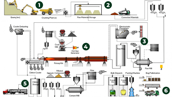
We have broken down the main 6 processes of a cement plant for you:
Stage 1
Raw materials are extracted from quarries by blasting or using heavy machinery. They are then transported to the crushing plants where its broken down into smaller pieces.
Stage 2
The crushed material is transported into the Raw Materials Storage usually by conveyor belts. It’s stored in blending beds and homogenised.
Stage 3
The Raw material is then added with the other materials needed to make the required type of cement. The mixture is grinded to a fine powder using grinding mills and ball mills, it is dried at the same time.
Stage 4
The dried mixture is then burned to around 1450°C in a kiln or lepol. A new product is created called clinker, this process is known as sintering.
Stage 5
The clinker is then cooled and stored in silos. It is then ground down even further to a very fine cement and further ingredients added depending on what cement is required.
Stage 6
Finished cement is stored in separate silos, depending on type and strength. From there it is distributed accordingly.
Power distribution design for cement plant
Power distribution system of a cement plant begins with the substation of the grid where power is received and ends with individual drives and points of usage. It is a large network consisting of elements like distribution transformers, MV/LV control panels, individual distribution switchboards and motor control centres (MCCs), switchgears for safety, regulation and metering of power used at various points, motors and their control gear, power and control cables, lighting, earthing and other components of the system.
Voltage and Frequency
Grid frequency is 50Hz in the UK and Voltage of transmission could be as high as 222 KV or 132 KV for large capacities and 66 KV, 33 KV or 11 KV down the line depending on MVA capacity of the substation.
The voltage of generation itself would be say 6.6 KV. It is stepped up for transmission; longer the distance over which power is to be transmitted higher the voltage of transmission to minimise losses in transit.
Distribution System Within the Plant
In a cement plant also there is a ‘mini grid‘ receiving power from main electricity grid and also from plant’s captive power plant. They have to work simultaneously and hence should be ‘synchronized’ when working in parallel, i.e., the voltage, frequency and phase must match.
Alternatively, captive power is used only to supply power to specific sections like kiln and one of the two major mills.
However, the present trend is to size captive power station large enough and to synchronize captive power with grid power. There was a time when Cement Plants found it cheaper to use their own Power as compared to grid power. In recent times however prices of both light and heavy oils have shot down and hence this situation may change again.
Normally, drives of following machinery would be medium voltage motors:
- Main crusher
- Raw Mill
- Preheater fan
- Coal Mill
- Cement Mill
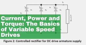
In the last 25 years, variable speed drives (VSD) have been used more frequently in the cement industry. The main reason was to save energy in the production process.
MV and LV Drives in a Section
Therefore, some sections will have only LV supply and others both MV and LV supply and also DC drives. One option is to step down voltage from grid voltage for the total plant in one place and lead HT lines from it to respective sections in which MV motors are used.
Synchronization of Grid and Captive Power
Even when parallel busbar system or ring system is not used, the grid supply and captive supply must synchronize and work in parallel or individually without disrupting power supply to any section of the plant.
Power Factor
Another important aspect is that of power factor. It’s important to know that:
- Induction motors work at varying lagging power factors depending on load.
- D.C. motors have unity p.f. on d.c. side.
- In case of synchronous induction motors, power factors can be altered between leading and lagging.
Power factor as close between 0.95 to 0.90 lagging is desirable to get maximum from power purchased from the grid station. Lower the power factor, greater the losses.
When power factor is unity, useful power available is: V × A × 1/1000 = KVA = KW. This means that if power factor is say 0.80, useful power available is: V × A × 0.8/1000 = 0.8 VA KW
Power bills are based on kWh consumed and charges for maximum demand are on KVA
Correction of Power Factor
Generally, correction of power factor is done by:
- Using individual capacitors for motors and by using ‘capacitor banks‘ in total sections.
- Using synchronous induction motors to correct overall power factor by running them on leading power factor.
Our team of experienced engineers can do this for you, contact us and we can arrange a site visit to assess.